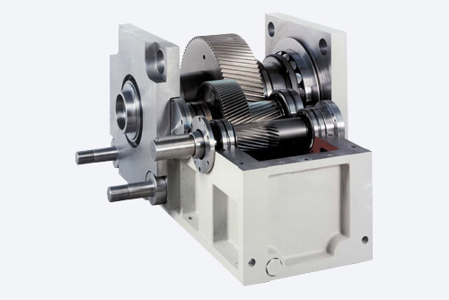
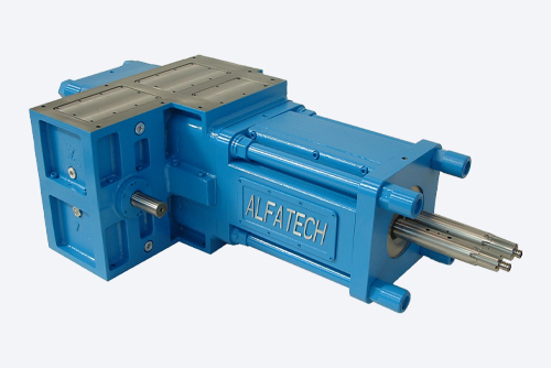
ALFATECH’s commitment to producing specific reduction gears for controlling single-screw and two-screw extrudersgrew over the course of long experience of studies and research into solving particular flowrate and application problems, cooperating with the most prominent domestic and international manufacturers of extrusion and co-extrusion systems.

Single-screw reduction gears
Developing this series is characterized by design and engineering innovations that fulfill the need for total reliability, which is obtained by rigorous processing specifications and checks of dimensions and the materials used in order to comply with technological specifications set during the design phase and confirmed by the relative and complex calculations that are able to reproduce the operating conditions of each reduction gear.
This is made possible by the dedicated RIDEST software programme in a Windows environment that is available on request as a technical support for our customers to enable them to select the reduction gear and determine the operating conditions for the load capacity, dynamic conditions of the elements, and constructional and lubrication characteristics.
Service factor for gears according to A.G.M.A. standards 218.01 and relative bibliographies for calculating fatigue stress at the base of the tooth and specific surface pressure.
There are also special algorithms to determine mathematically the geometric factors of correct toothing:
• efficiency of gears
• thermal capacity
• heat exchange
The elastic line of all shafts shows in the following diagrams:
• arrow
• bending moment
• shear strain
• bending stress
• bending and torsional stress
• shearing stress
• theoretic duration of all bearings
• peripheral speed of gears
• bending critical speed of the fast shaft
• tensile stress on thrust-bearing tie rods
• dynamic loads on foundation bolts
They have been conceived according to the modular system. They also permit horizontal or vertical assembly according to the specific application and are characterized by:
• quality cast-iron case divided into two halves
• carbon steel front plate set up for connecting the extruder
• carbon steel thrust-bearing rear plate
• carbon steel thrust-bearing tie rods with front extension (on request) for anchoring the extruder, alternatively to the flanging, with the front plate
• forged, hardened and tempered steel alloy gears with helical toothing with ground profile. The DIN<=6 (ISO<=5 or AGMA>=11) quality prescribed by technical specifications is ascertained by rigorous electronic checks of the profile, helix, pitch, eccentricity, etc that are documented by the respective diagrams;
• slow shaft made of alloy and tempered steel with axial hole that enables the extrusion screw to pass through so as to extract the screw through the reduction gear, which is very advantageous, especially in applications with coextrusion, avoiding dismantling of the elements downstream of the extruder or advancing along the entire line;
• quick shaft with cylindrical end set up for direct coupling of the motor both at the rear and the front;
• screw coupling bush made of alloy and tempered steel with inner profile that is grooved or drilled as requested. This flexibility enables the reduction gear to be selected according to the torque that needs to be transmitted rather than screw diameter. In other words, a reduction gear can be coupled with different types of extruder.
In addition, the bush can be fitted at the front or rear, depending on the application requested;
• each shaft is supported by the pair of radial roller bearing and by an axial bearing so as to ensure the theoretical calculated working life of all the bearings regardless of the direction of the axial loads that vary according to the rotation directions of the bearings.
Particular care is taken over the interchangeability of the axial bearing of the slow rod that is located in the rear part, facilitating possible maintenance without detaching the extruder. In addition, the same bearing is available in 4 sizes for each type of reduction gear so that the right bearing can be selected to ensure the requested theoretical working life.
The variability of operating conditions and fitting arrangements do not enable a lubrication standard to be defined that accordingly allows for forced circulation lubrication by an electric pump and splash lubrication in an oil bath.
In some cases and in particular environmental conditions, the oil is also cooled by a heat exchanger.
Our Technical Department will be happy to advise you on the best lubrication system for the specific application.

Two-screw reduction gears
Using the same planning and technological method developed from the design of single-screw reduction gears, we have also developed the line of two-screw extruder control reduction gears characterized by the kinematic arrangement of the gears that guide the inner screw (motor side) so as to eliminate the radial dynamic loads caused by the gears and to increase the life/durability of the bearings. This new condition also means that the screw can operate at high speeds.
Service factor for gears according to A.G.M.A. standards 218.01 and relative bibliographies for calculating fatigue stress at the base of the tooth and specific surface pressure. In addition, special algorithms have been implemented to determine mathematically the geometric factors of correct toothing:
• efficiency of gears
• thermal capacity
• heat exchange
The elastic line of all shafts shows in the following diagrams:
• arrow
• bending moment
• shear strain
• bending stress
• bending and torsional stress
• shearing stress
• theoretic duration of all bearings
• peripheral speed of gears
• bending critical speed of the fast shaft
• tensile stress on thrust-bearing tie rods
• dynamic loads on foundation bolts
The main characteristics of the reduction gears controlling two-screw extruders are:
• cast iron case
• hardened, tempered and ground steel alloy gears with DIN< = 6 quality
• SKF or FAG rolling bearings
• Multi-stage axial bearing
• Support of axial bearings of the screws with steel plates connected by tie rods
• Forced lubrication by pump and and exchanger to cool the oil positioned on a plate to be fixed to a wall below the reduction gear in the rear part
• Axial load control (only outer screw) by load cell
• Protrusions of slow shafts and extruder cylinder connection as per your drawings
• Protrusion of inlet shaft from extruder side
Application sectors
Extrusion of plastics for use in food and pharmaceutical industries


